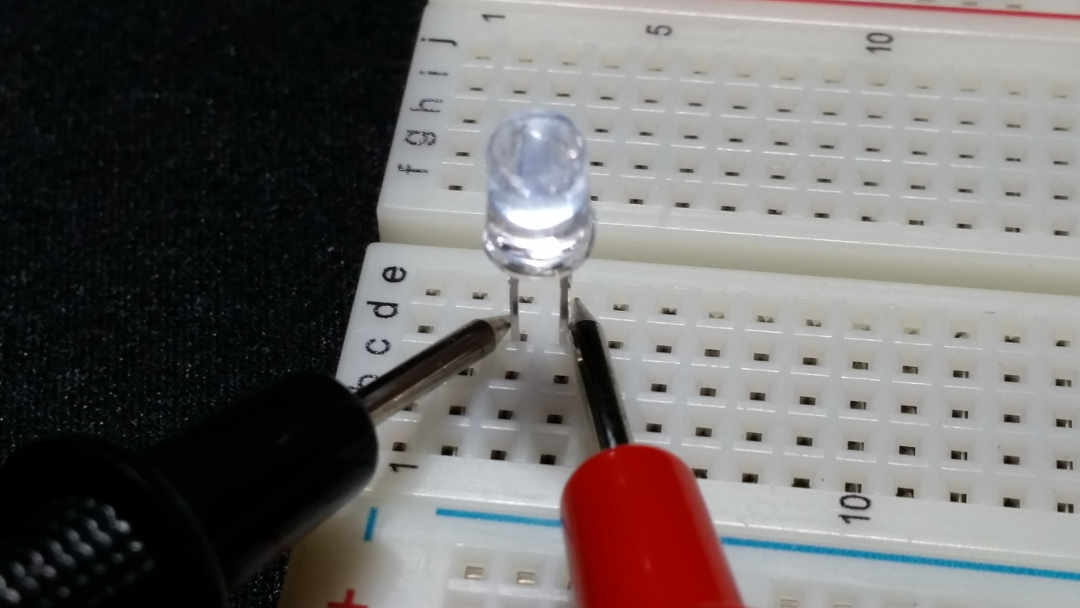
Here, we’ll hook up a second LED with the anode facing away from Pin 4 (instead, towards 5V) and the cathode facing toward Pin 4.
#Led anode cathode code#
#Led anode cathode serial#
It allows you to monitor the RGB decimal value or the duty cycle of PWM signals through the serial monitor of the Arduino IDE. The other lines in the code are for monitoring purposes. These lines program the Arduino Uno to adjust the duty cycle of the PWM signals based on the voltages across the ADC channels. Then it converts the values into a (0-255) range since the ADC uses 10-bit resolution which ranges from (0-1023) but the PWM function of the Arduino Uno uses a (0-255) range. This part of the code tells the Arduino Uno to read the voltage across the wiper terminal of the potentiometers/trimmers through channels A0, A1, and A2. These lines configure the digital pins D9, D10, and D11 to be the PWM output pins.

Int RGBLED_BluePin = 11pinMode(RGBLED_RedPin, OUTPUT) Previous_PWMValue_GreenPin = Pot_GreenPin If (Threshold_PWMValue_RedPin >= 10 || Threshold_PWMValue_GreenPin >= 10 || Threshold_PWMValue_BluePin >= 10) Threshold_PWMValue_BluePin = abs(Pot_BluePin - Previous_PWMValue_BluePin) Threshold_PWMValue_GreenPin = abs(Pot_GreenPin - Previous_PWMValue_GreenPin) Threshold_PWMValue_RedPin = abs(Pot_RedPin - Previous_PWMValue_RedPin) Sometimes you get unstable output due to jumper wires not properly connected, poor quality breadboard, or poor quality potentiometers. This section is for serial printing the RGB decimal values. Use this code for RGB LED COMMON ANODE and comment the code for COMMON CATHODEĪnalogWrite(RGBLED_RedPin, 255-PWMValue_RedPin) ĪnalogWrite(RGBLED_GreenPin, 255-PWMValue_GreenPin) ĪnalogWrite(RGBLED_BluePin, 255-PWMValue_BluePin) Use this code for RGB LED COMMON CATHODE and comment the code for COMMON ANODEĪnalogWrite(RGBLED_RedPin, PWMValue_RedPin) ĪnalogWrite(RGBLED_GreenPin, PWMValue_GreenPin) ĪnalogWrite(RGBLED_BluePin, PWMValue_BluePin) Serial.begin(9600) // initialize serial communications at 9600 bps That way, you can have a balance between the brightness of the internal LEDs. But if you have access to the datasheet of the RGB LED that you're using, check the forward voltages of internal LEDs and from that, you can calculate the right resistance of the resistors that you're going to use.
#Led anode cathode series#
Note: In this example, we just used the same resistance value for the RGB LED series resistors. The cathode pin of the RGB LED is connected to the GND pin of the Arduino Uno. The D10 pin controls the intensity of the green LED and D11 controls the intensity of the blue LED. As you can see in the image above, the D9 pin controls the intensity of the red LED of the RGB LED. The ADC of the Arduino Uno reads the analog voltage across the wiper terminal of the potentiometers/trimmers and based on that voltage, the Arduino Uno adjusts the duty cycle of the PWM signals generated at the PWM pins D9, D10, and D11. Basically, what happens here is that we have 3 potentiometers/trimmers connected to the A0, A1, and A2 ADC channels of the Arduino Uno. They're all connected through the jumper wires that we have. We have here a common cathode RGB LED, an Arduino Uno board, 3 potentiometers/trimmers, and 3 resistors.


 0 kommentar(er)
